This time I’ve been dealing with what I though was frost heave but turned out to be expansive clay.
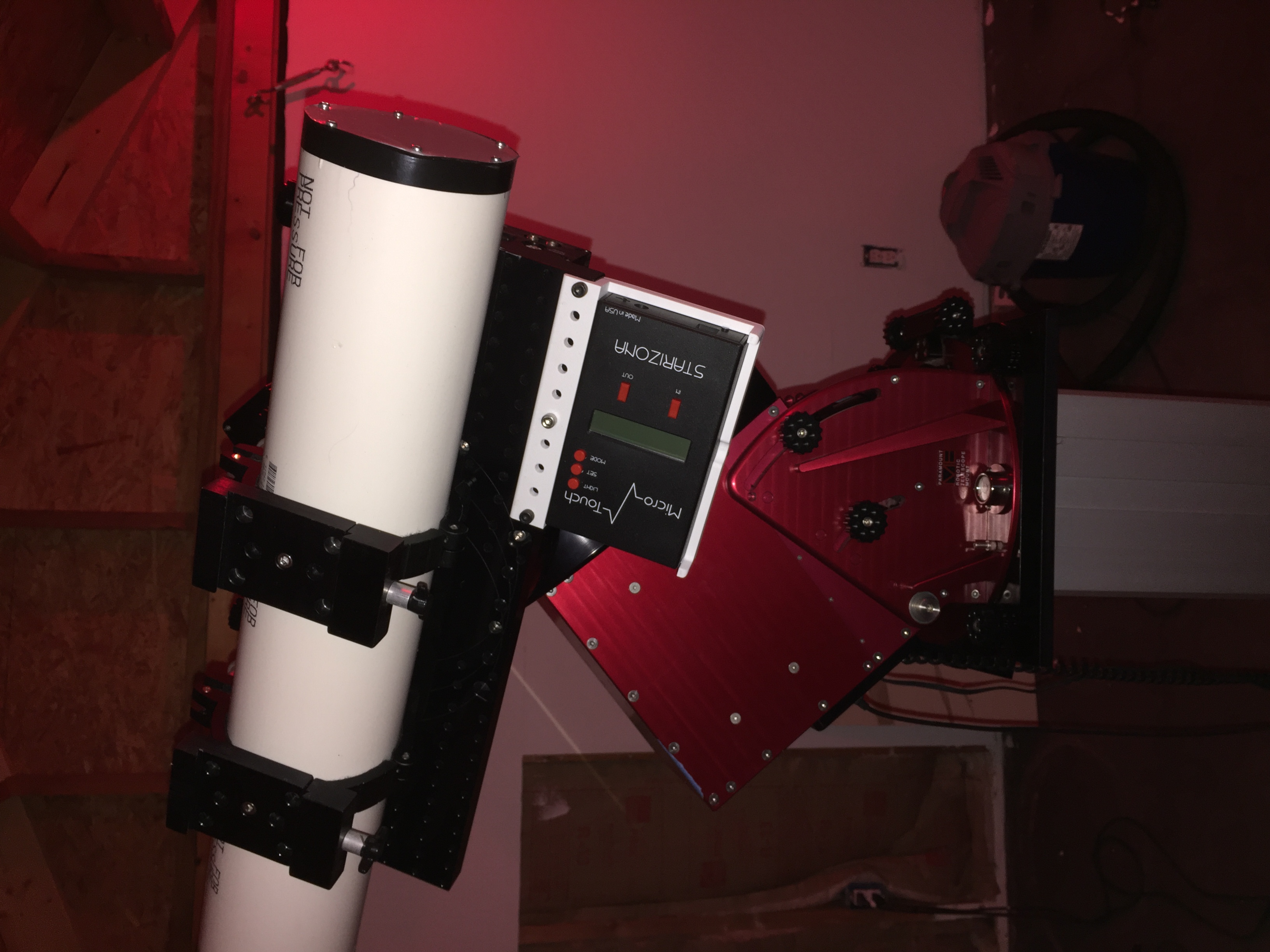
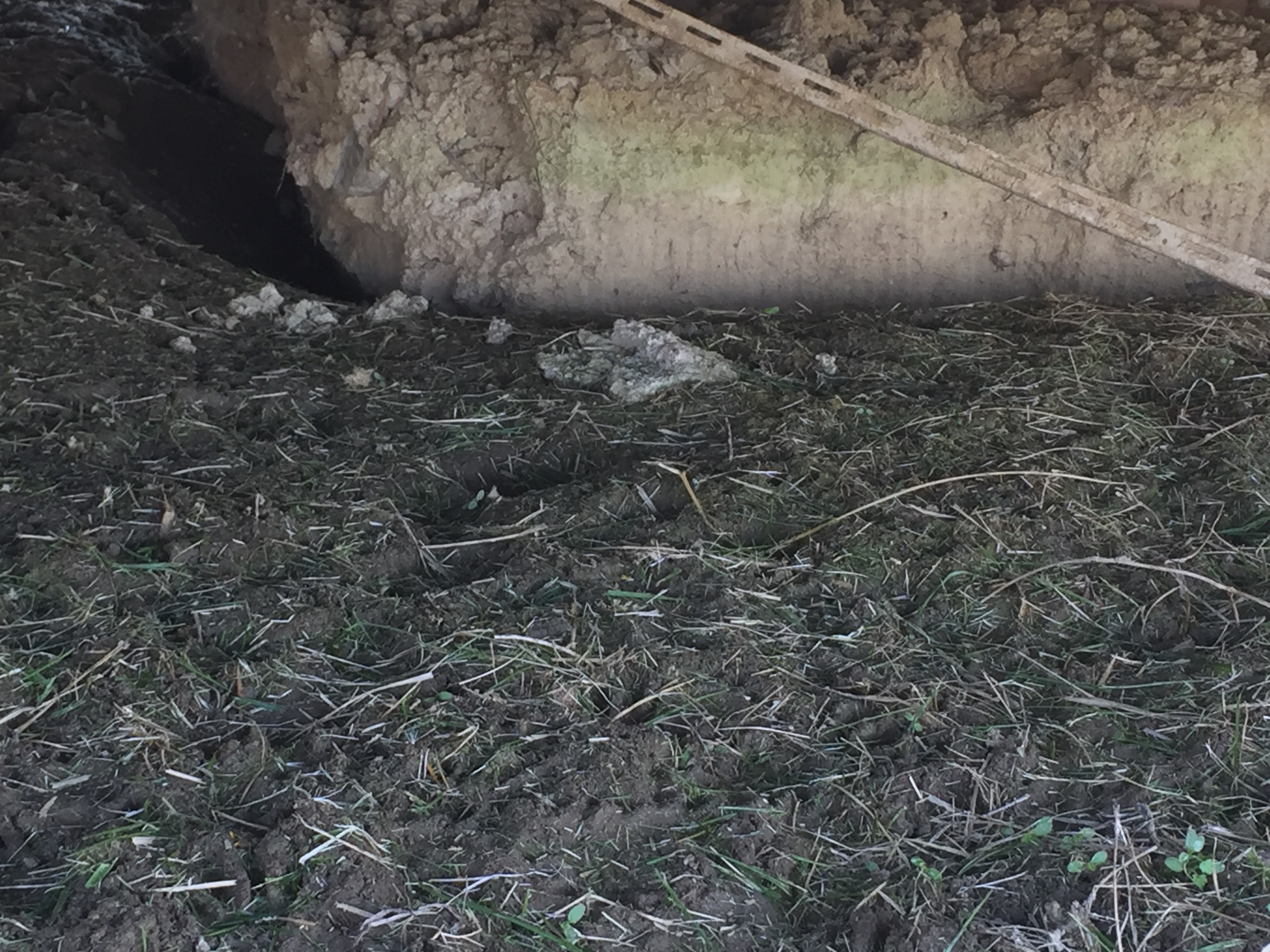
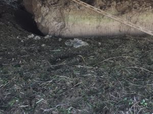
My first sign I noticed was how raised my observatory was as seen here. But also you can see the pier foundation raised so I took a closer look
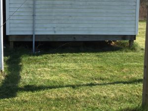
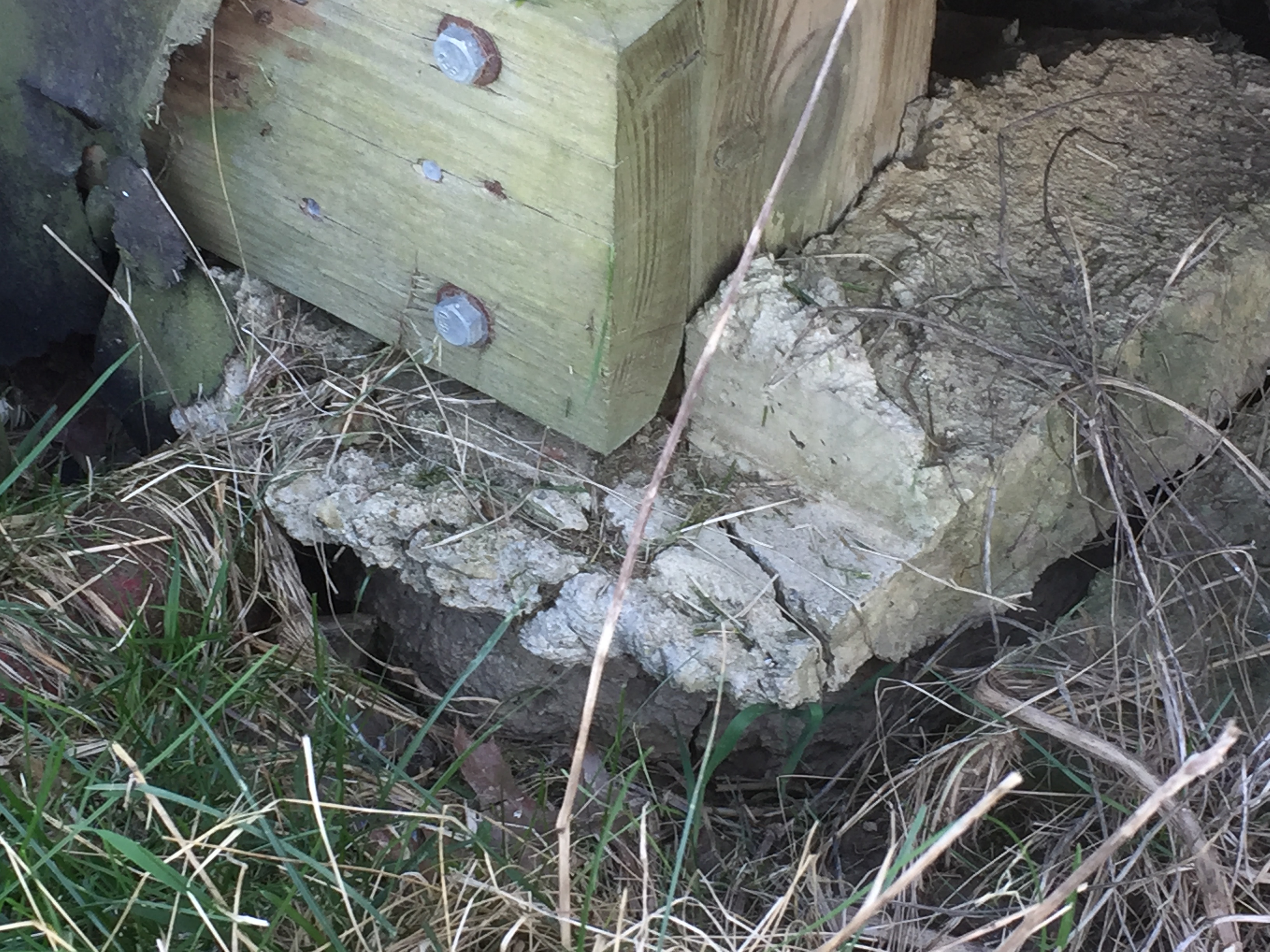
Here you can clearly see the foundation of the pier lifted as well as the footing of the building itself. This is not good
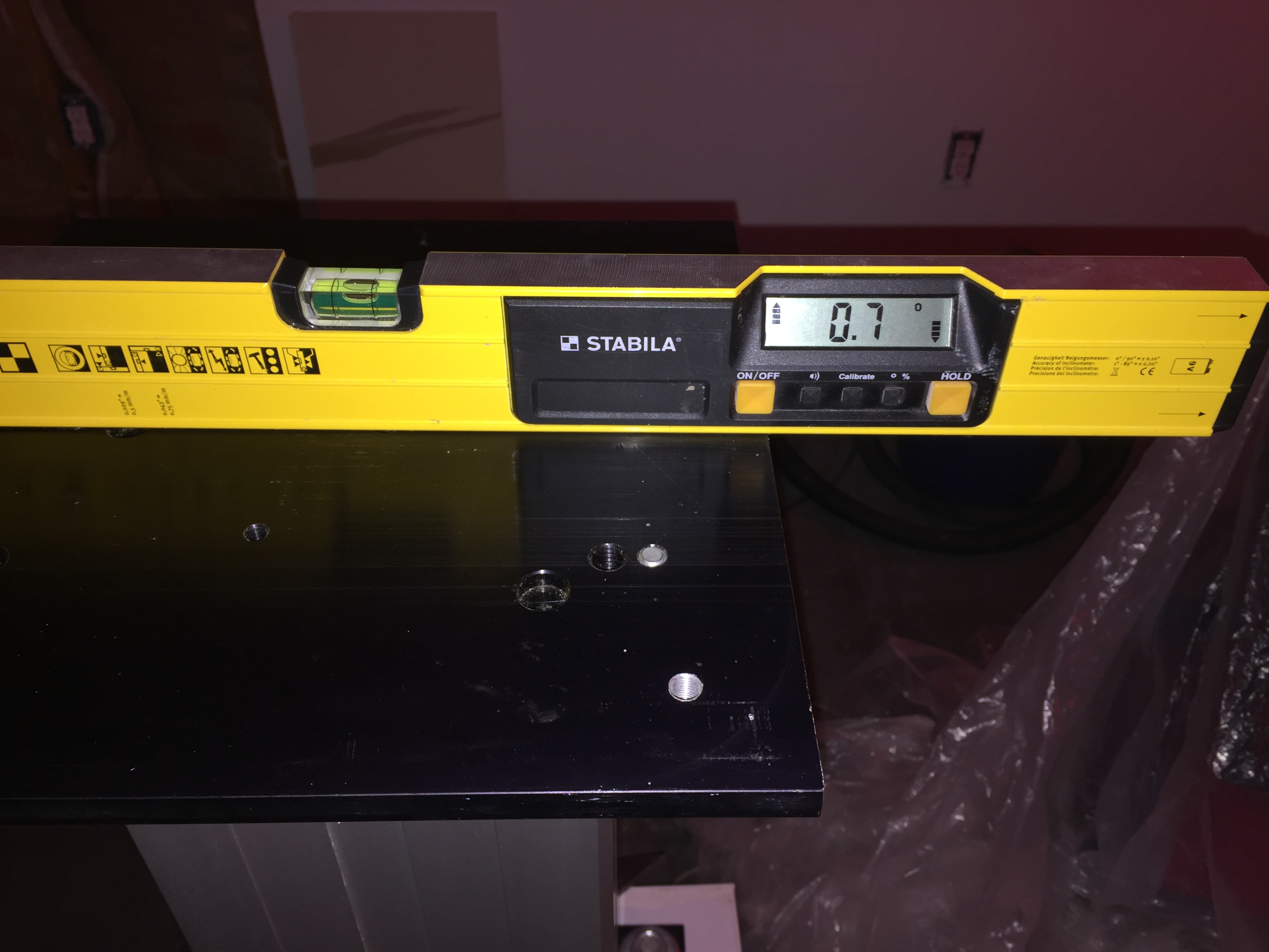
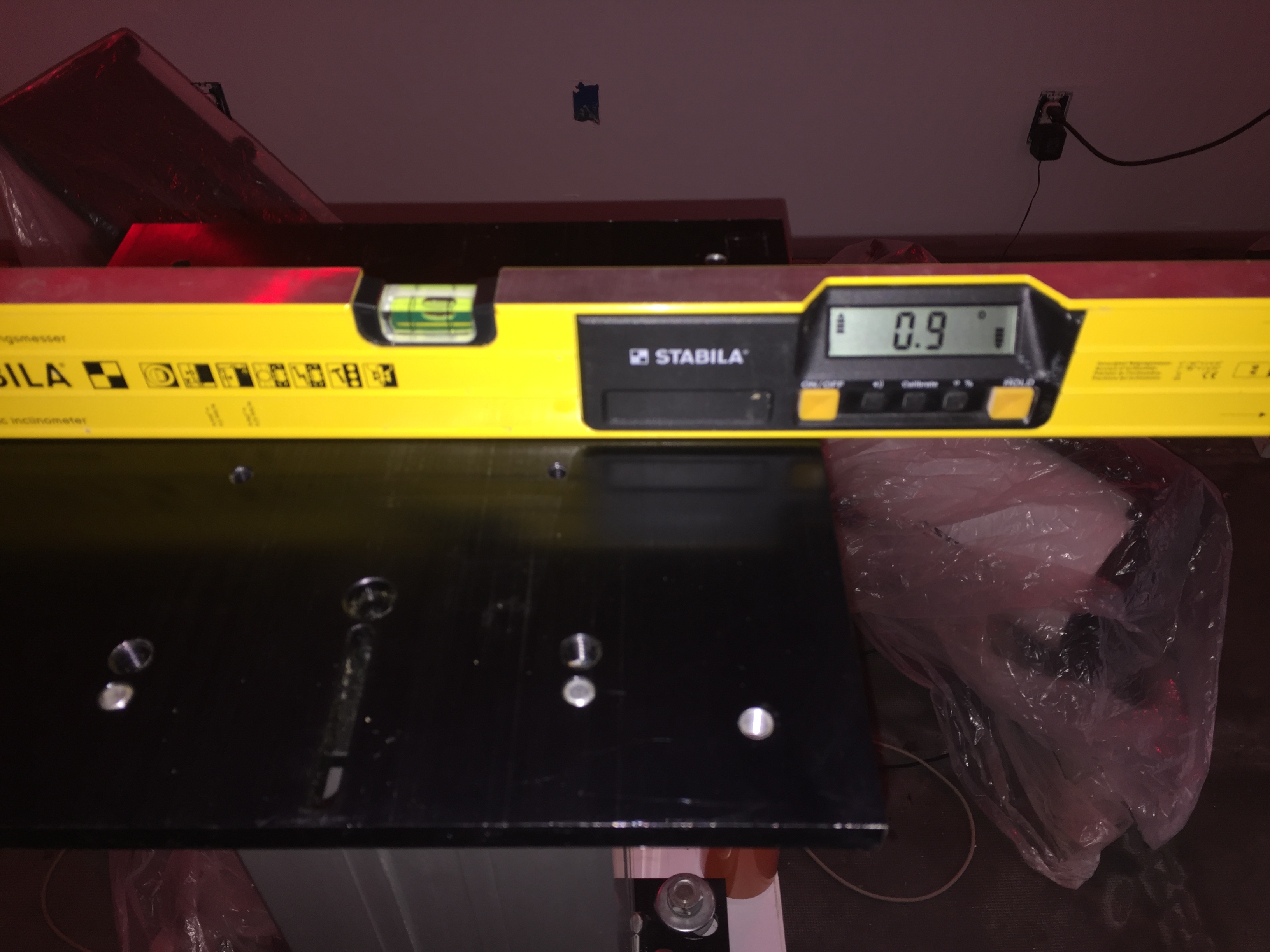
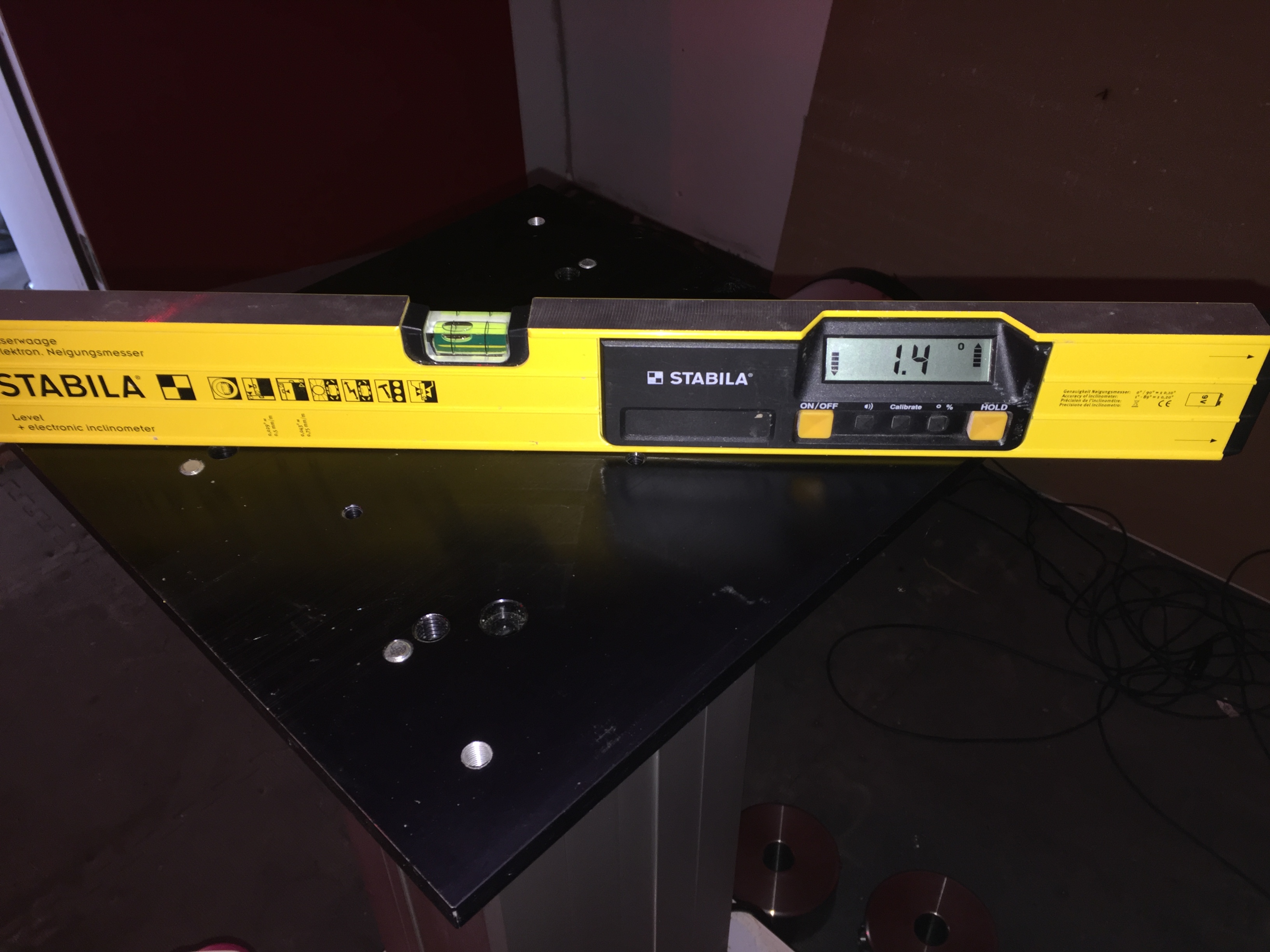
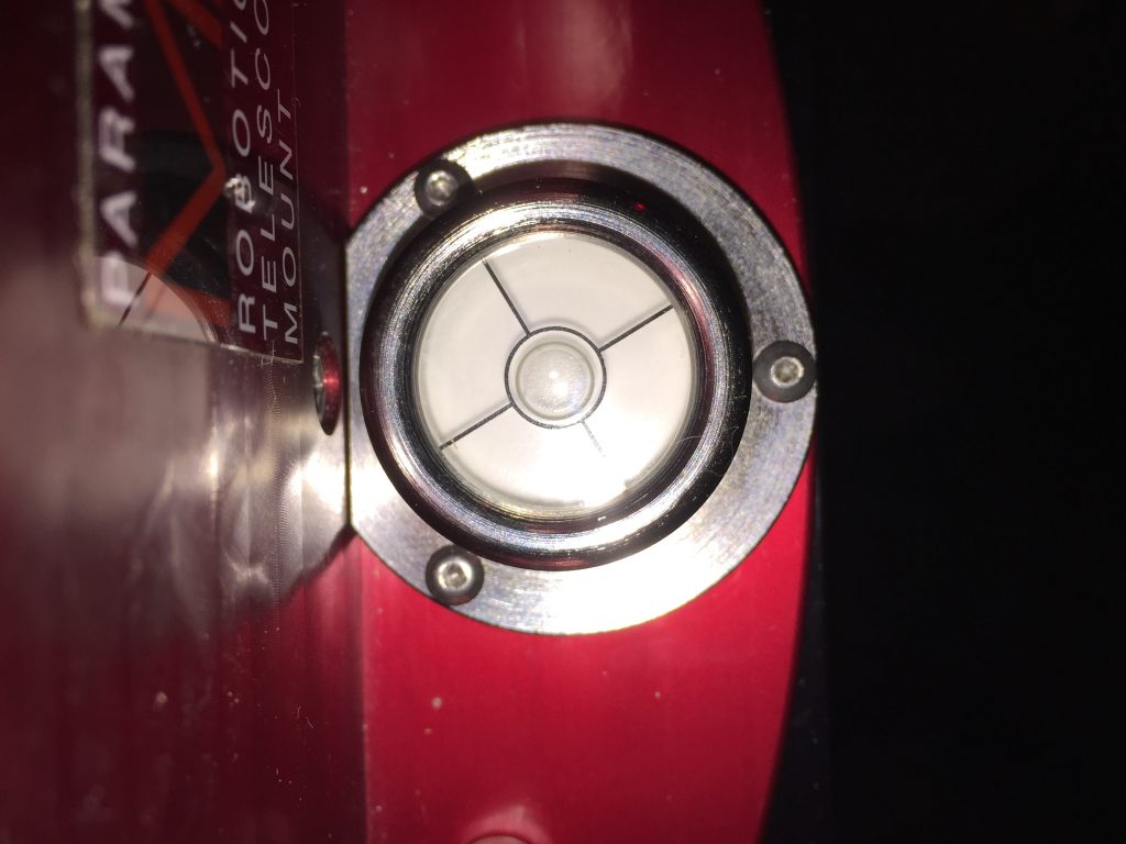
I using the trust level I removed the mount and checked and it has up to a 1.4 degree tilt now
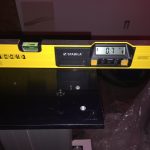
North-South
East-West
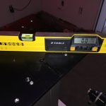
NW-SE
NE-SW
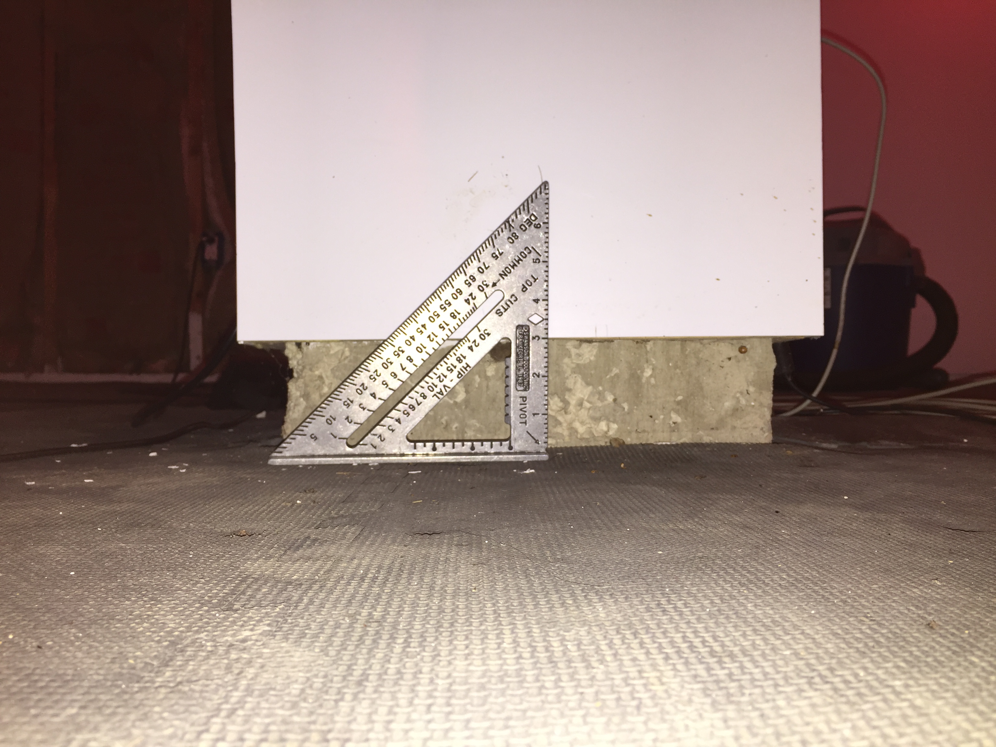
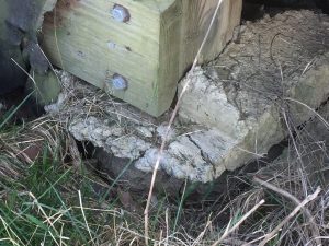
But even more the entire pier is raised 3″ that white cover over the concrete used to just touch the floor
So I monitored the pier for shifting over a period of a month and contacted a foundation repair company to check out the situtuaion and they said yes it was expansive clay and it had raised and titled it. Expansive clay was common in my area (if I had known that I would have prepared the ground differently) The quoted roughly 3600 to stabilize the pier by driving two piers down to bed rock but they would tear up the observatory flooring and it would be up to me to replace it. Not having 3600 plus floor repairs I had a pass.
I posted on the bisque forum and got some good replies including this is not all that uncommon.
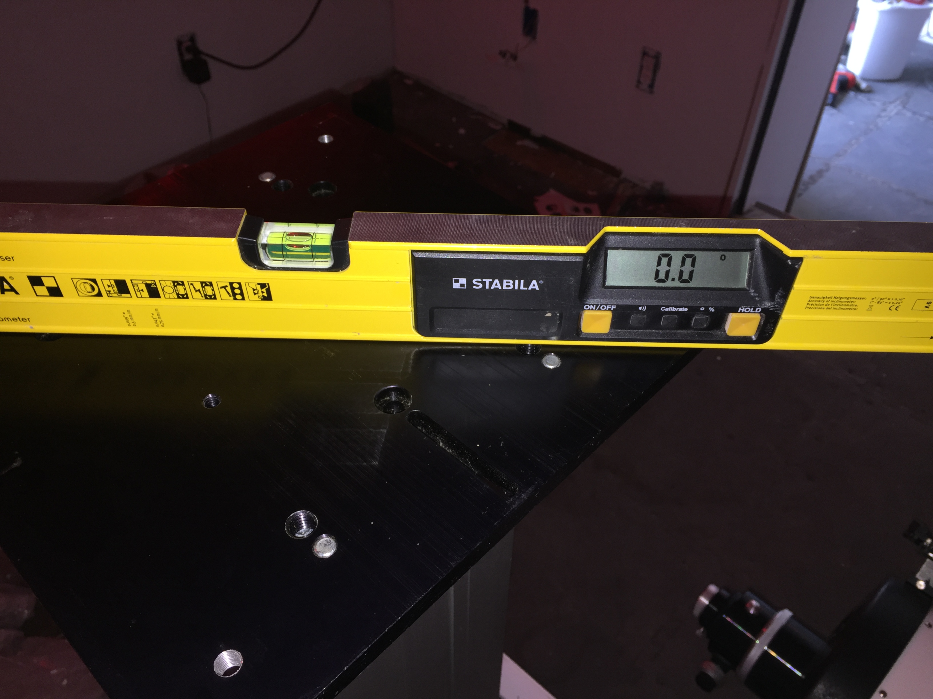
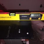
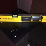
So first step was the re-level the pier which I did as seen here
The slight off center bubble is due to camera angle, it is dead on center bubble.
I then monitored that for a while and there have been minor shifts due to wet/dry times.
Based on that feedback what I will need to do is a full t-point calibration run (the more points the better). after than a normal calibration will account for any further changes to the level of the pier. Good news.
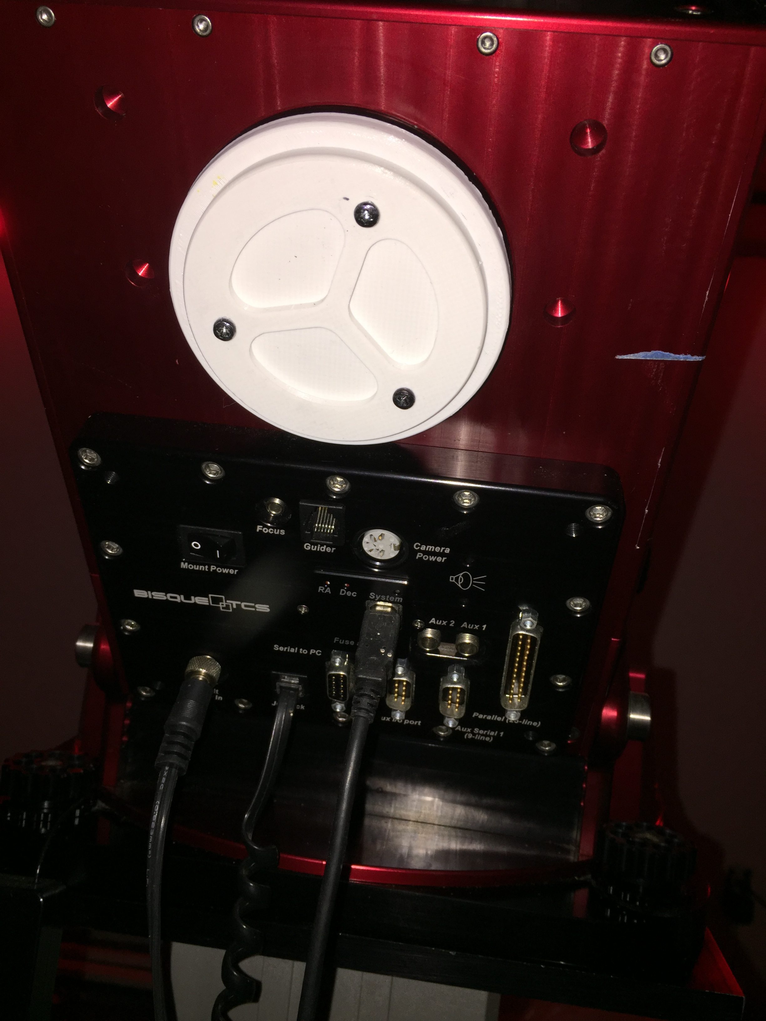
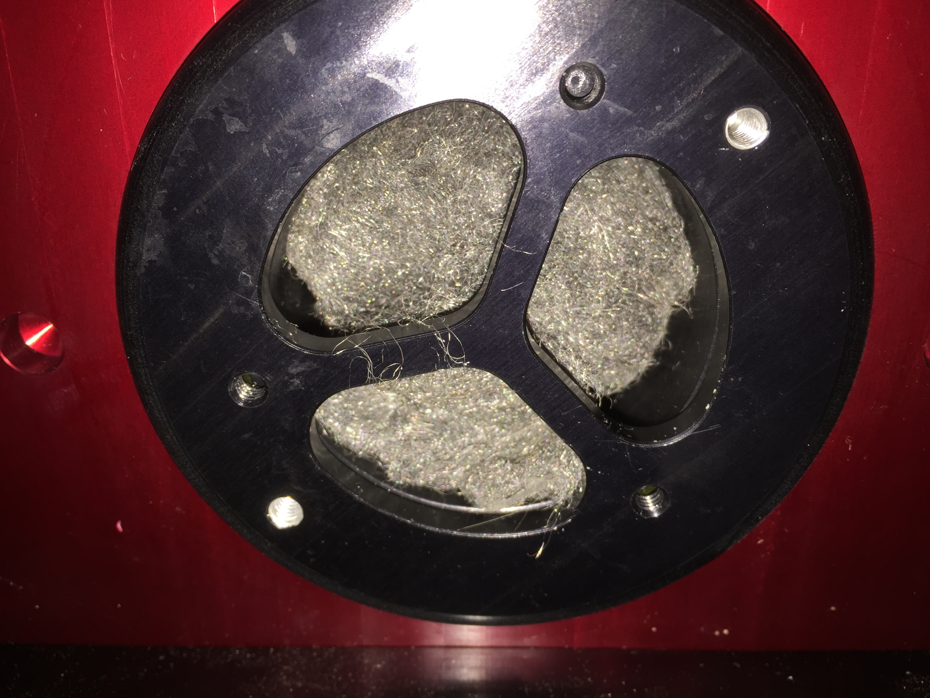
My next task is to redo my thru mount cabling which includes a 3D printed cover for the exit point of the cables to prevent another mouse attack on my Paramount.
So to be continued…